The concept for the track
- Follow the prototype as closely as possible,
- No visible wire connections
- High detail level
- Provide reliable running
Pattern making
We had a search around for suitable rail, and found that Tenmille produce a flat bottom rail which is suitable.
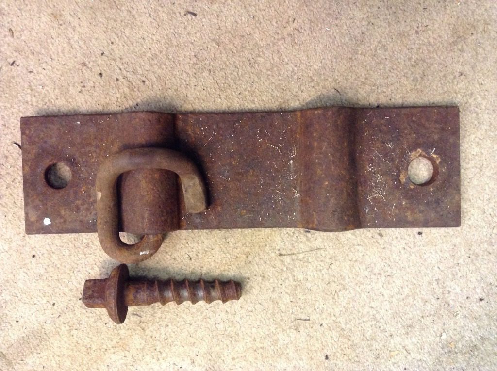
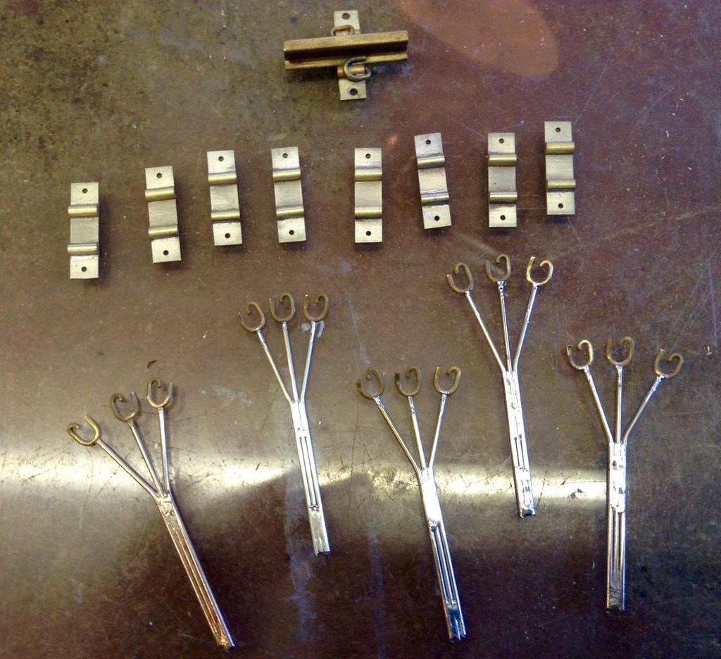
Working from the full size fixings we produced a selection of base plates from 0.9 nickel silver plate and half round rod to simulate the elastic rail fixing point.
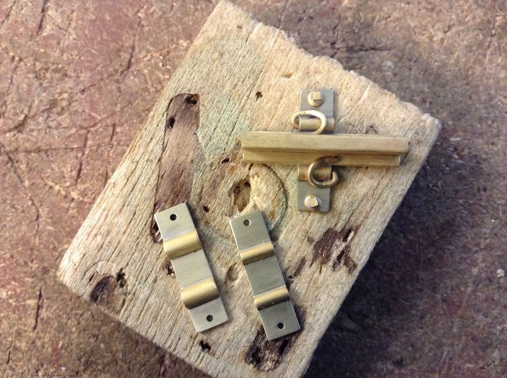
The first two plates didn’t quite fit the size because the half round rod is from a well known supplier, and not of the correct size.
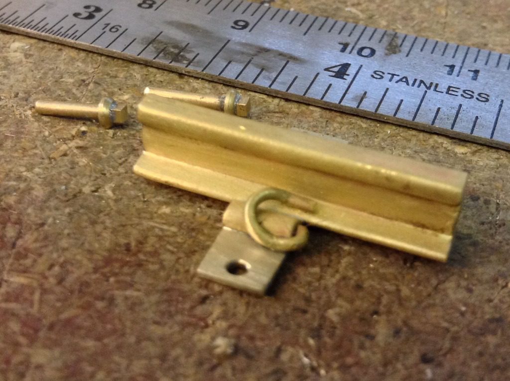
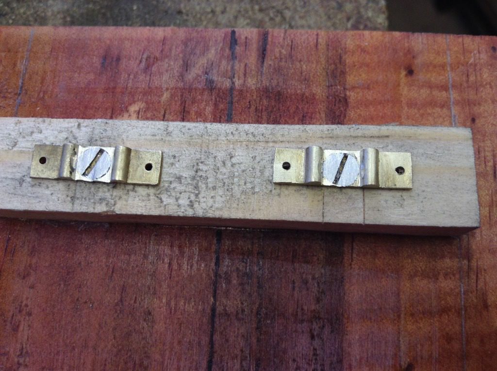
The completed one in the photo below is about right, this used a half round section machined from a 3/32 bar which is to scale size.
The elastic fixings need a bit more work to lengthen them slightly, using a simple bending jig which is easily modified.
Making these parts gives us the feel for the size of track components, as most of our experiences to date has been in 7mm, and it’s surprising how large the components are.
The screws will also act as the power feed points.
The next stage is to produce some patterns of the plates, bolts and fixings ready for lost wax casting, and start looking at developing the components for the points.
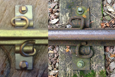
An interesting side-by-side comparison shot, just a few little tweaks to do and we are almost there.
Having finally settled on a track section that’s as close as Bredgar’s, the patterns for the plain track base plates have been constructed.
We’re still looking at the various differences with the point work before these patterns are started, but as we are getting close to cutting wood for the baseboards, these will be needed shortly.
Test construction
A small length of track was created to test the assembly method.
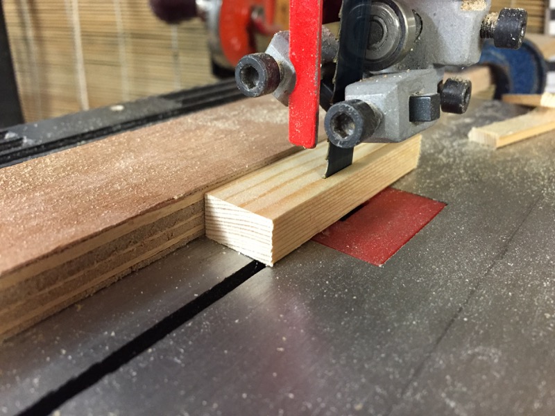
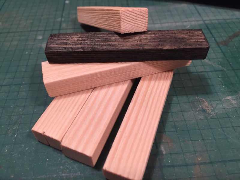
First up some pine was cut to size.
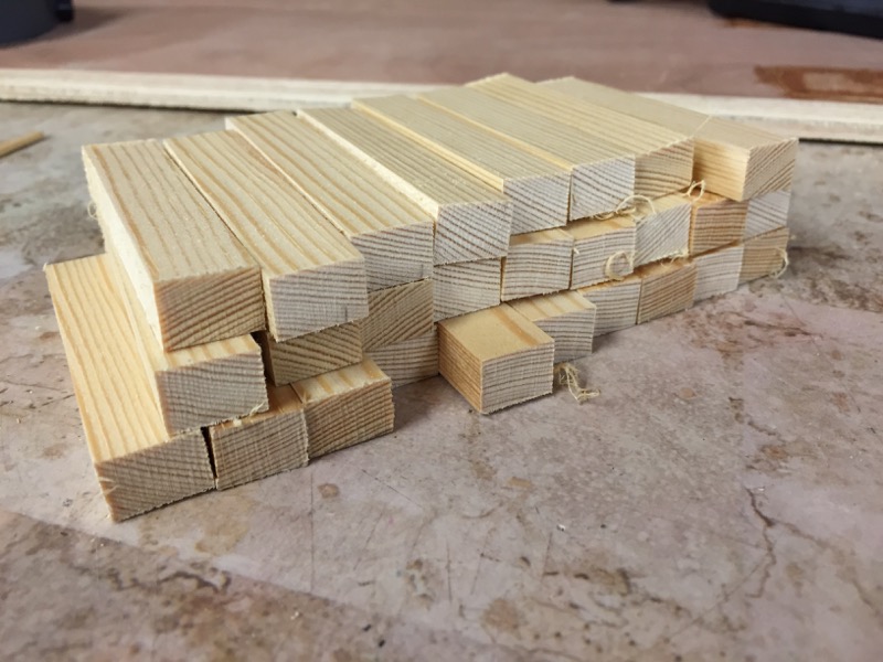
The pine sleepers are scale size and glued to a suitable lump of flat board. A small amount of distressing with a wire brush has given the surface some grain effect, the colouring of the sleepers will be completed once the track is fixed. Firstly a centre line is drawn on the board, and next the sleepers are glued to the board.
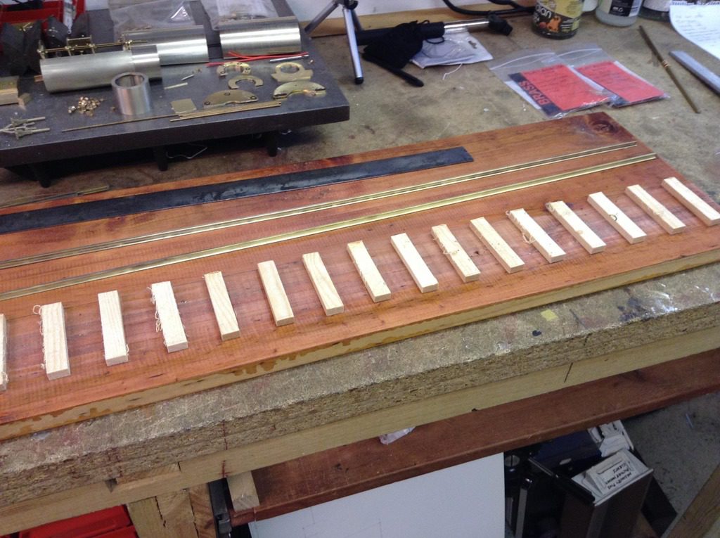
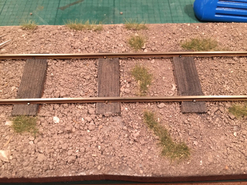
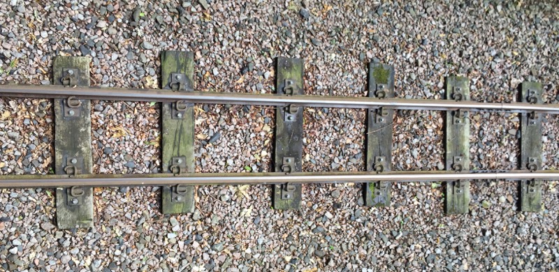
We have purposely made the spacing uneven and slightly off centre, this is prototypical when you look closely at the track at Bredgar (see photo below).
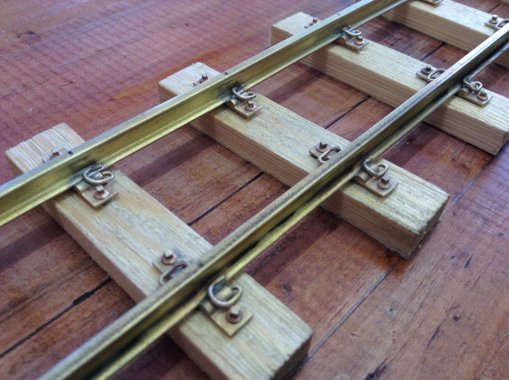
Next the rail, which is code 215 which matches the prototype, is marked for the plate locations from the sleeper centres, for this test section we are using some brass rail which with we had spare as we only have just enough nickel silver rail to complete the layout.
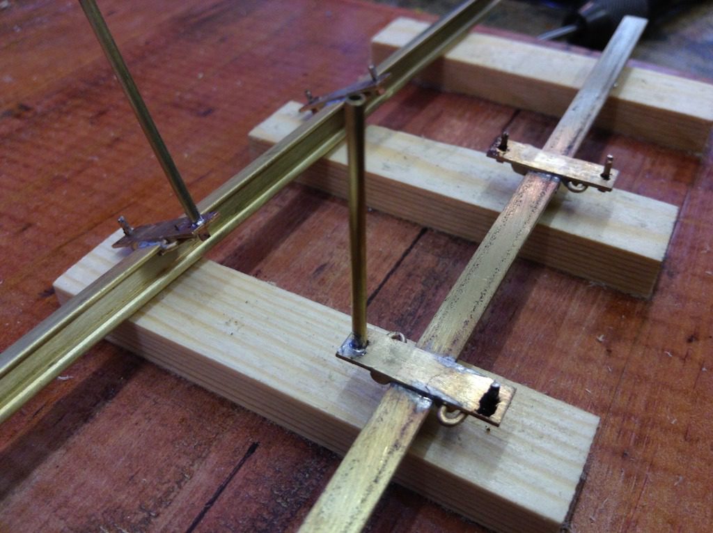
The plates are then soldered in place followed by the clips and dummy screws, and then the power feed rods which are tubes that solder to the bottom of the screw and run through to the underside of the baseboard. One of the early considerations was to have no visible wires showing on the layout.
A simple jig was made to drill the four holes to locate the screws that protrude through the plates. Using the centre line on the track base and on the jig the holes are drilled.
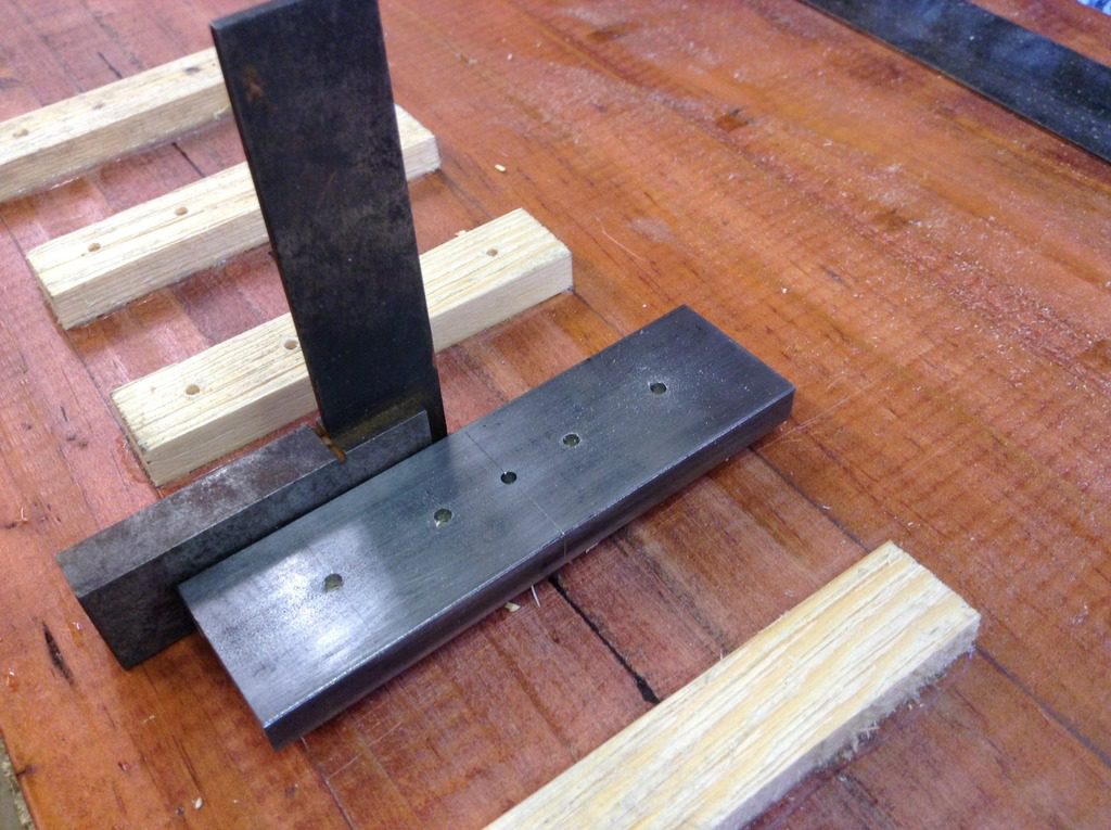
This then gives us self gauging rail as we assemble the track.
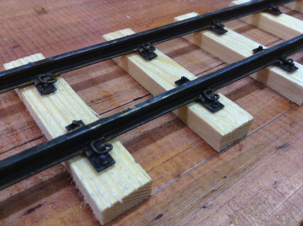
The rail ends at base board joints are always vulnerable, by using some small countersunk brass screws and drilling a countersunk a hole in the plates the rail can be soldered in place which gives a very strong joint.
Before the rails are glued in place some blackening liquid is applied which gives a base for the weathering.
Some experiments with track colouring have already been done on another 16mm project, which features a much lighter weight industrial railway using spiked track.
Sleepers cut and stained.
Ballasted using sieved samples of the actual ballast of the prototype.