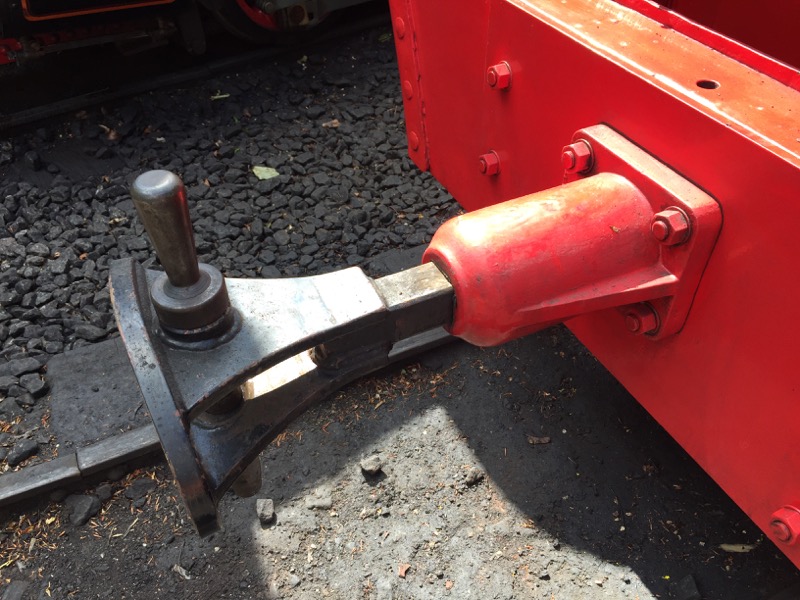
One of the common items of the stock is the couplers used on the locos at Bredgar.
So we made patterns for these.
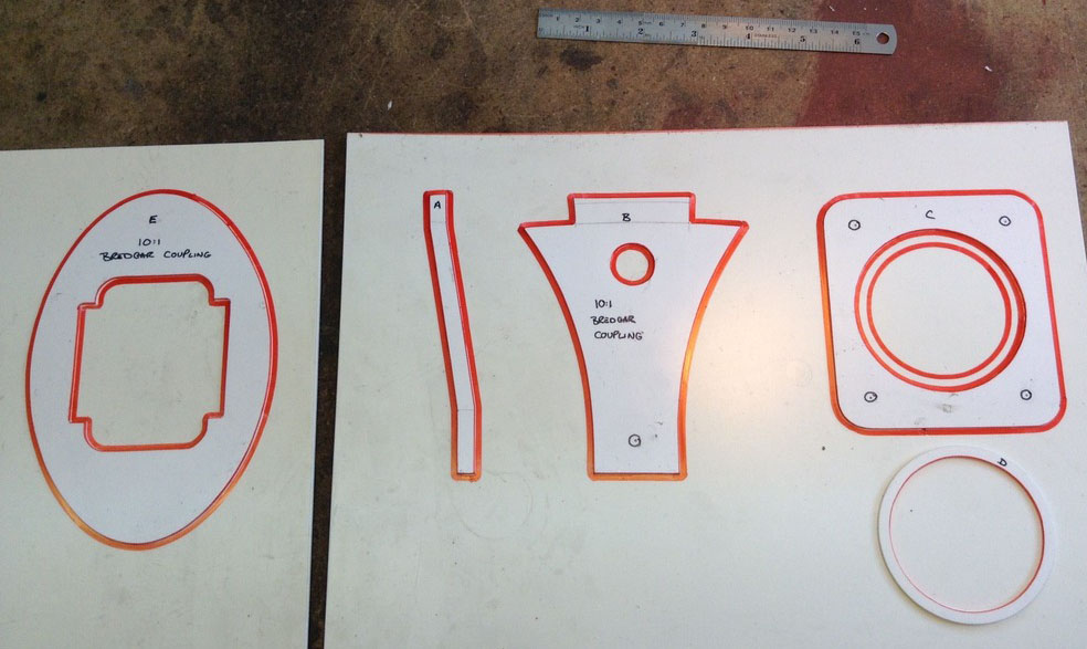
Patterns constructed.
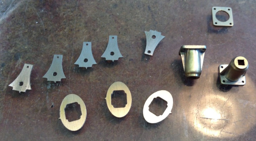
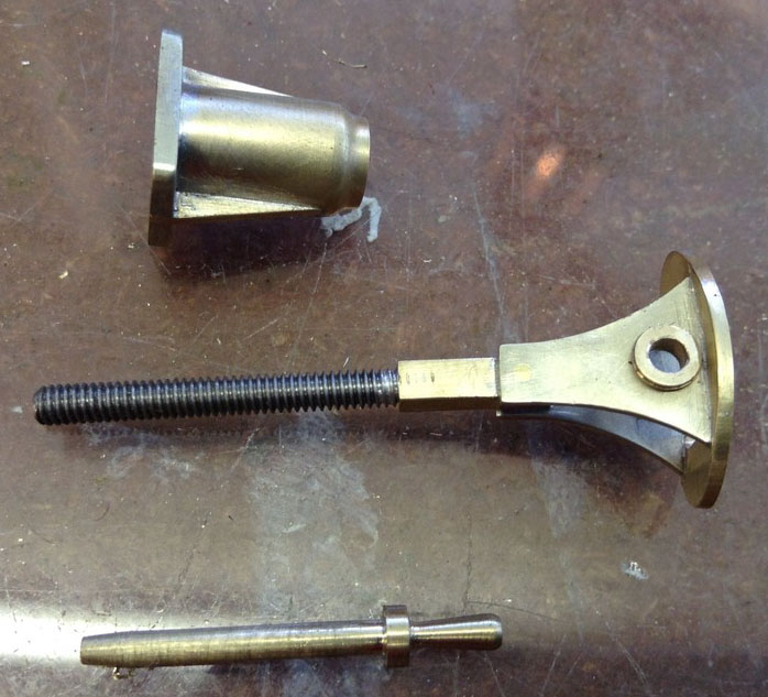
Prototype assembled.
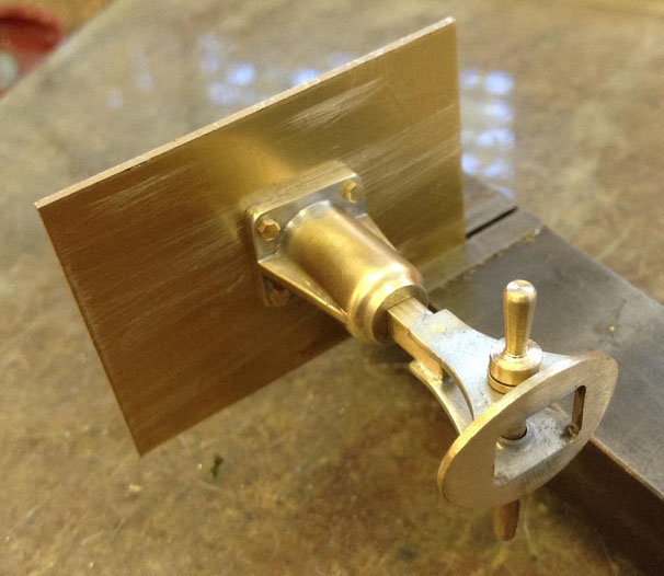
The opportunity was also taken to make a coupling head that swivels for use on our garden rail stock, as the fixed headed one will be fine on FSIJ but we need some flexibility with the tighter radius curves on the garden railway.
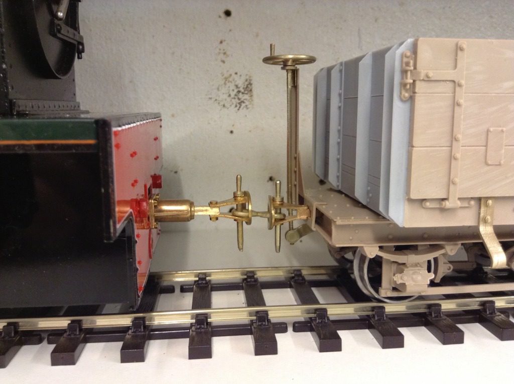
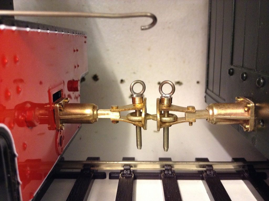
Wagon coupled to a garden rail loco fitted with the Bredgar couplings. The height of the coupling on the wagon is correct for Bredgar stock, the coupling on the loco is the height for Accucraft. In light of this difference our garden rail group will fit the coupling to the Bredgar height.
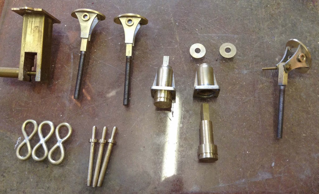
It looks like these couplings are going to be popular for garden use, so to make shunting easier we made some test pins with loops to help coupling and shunting, if successful we will cast them.
Automatic couplers
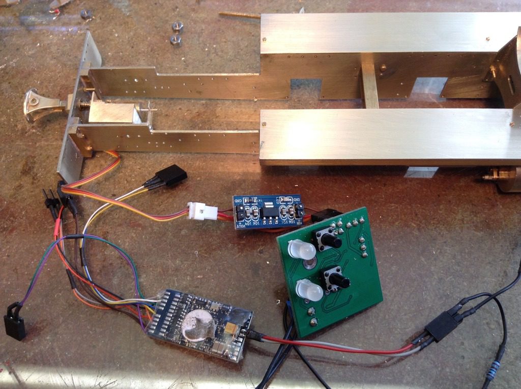
One of the requirements with the layout is that the couplings are automatic, and can be controlled via the DCC system.
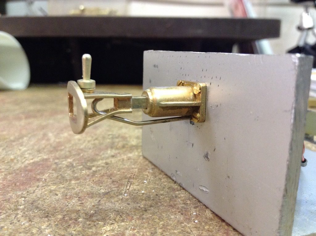
Modifying them to fit is a work in progress, so far we do have a working coupling which will need some refinement.
The bar fitted is counterbalance on the rear of the coupling, so that the bar is always in the closed position.
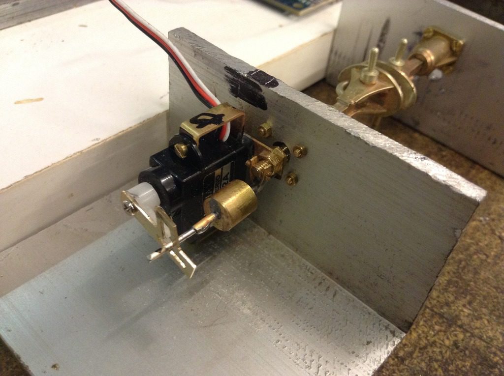
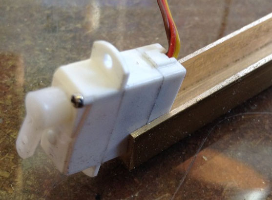
The first drive system did not work, the small motor could not lift the arm, the idea was good as with a small motor, this would fit easily into all the rolling stock and driven via the function output on a small sound chip.
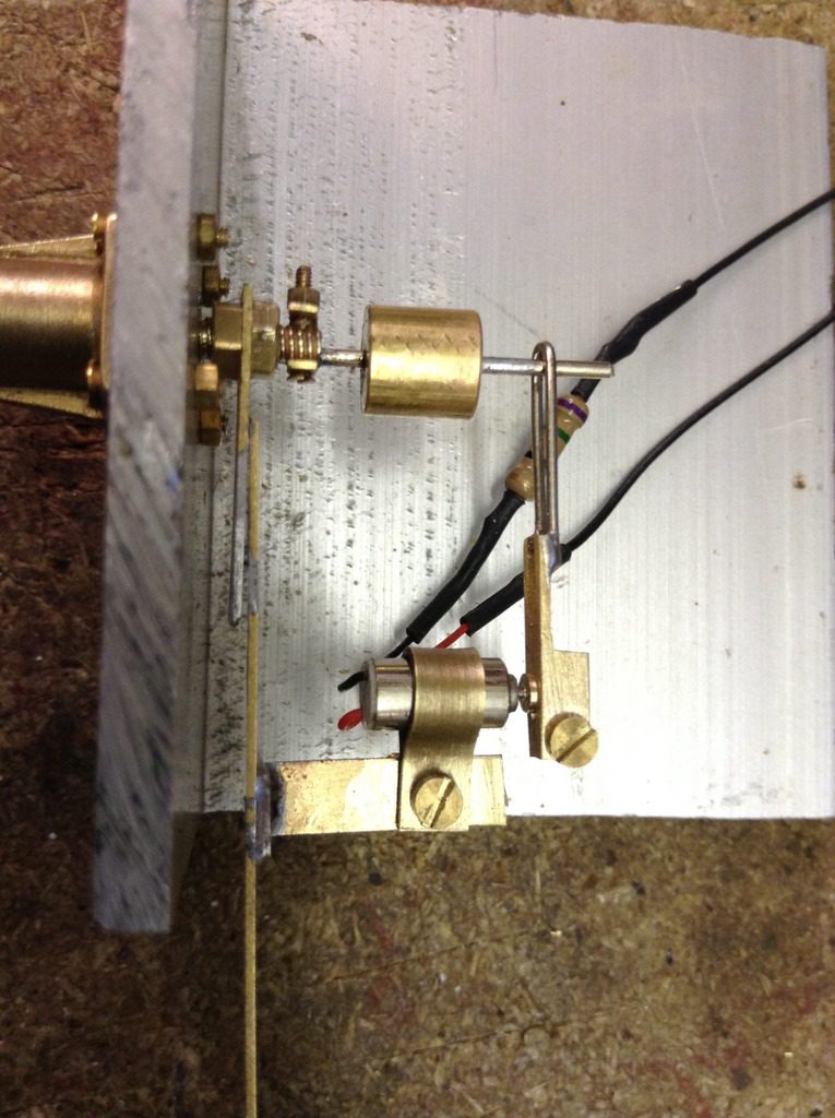
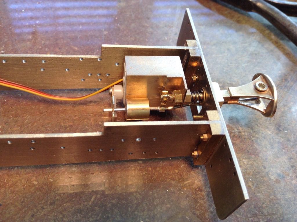
A revised version using a servo was created.
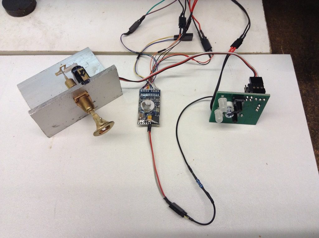
This one with a servo does work, as this clip shows. Driven via a Locsound XL chip which is a bit large, so we are looking at some sort of interface to drive the servo via a function output on a smaller chip.
The spec for the layout calls for the locos and rolling stock to be fitted with auto couplings operated via the DCC system. We have already developed the Bredgar couplings which work with a small servo, this is great as the ESU XL chips which will fit into the larger locos have function outputs for the servos. The problem with these models is the XL chip won’t fit into the Darent models, so the standard V4 chip which will fit can’t drive the servo on its own, so with the help of Duncan Mcree at Tam Valley Depot the Singlet ll servo motor driver can be linked to the chips. The Singlet range is designed for servo point operation and is only 1.25″ square. We can operate both couplings from a single servo but as sometimes double heading is required, independent control will be needed so two Singlets will be needed. The function output from the chip is a Logic one which needs the wire soldered on, and with the help of the programer its just a case of mapping the function and assigning it to an unused F key.
This video shows it working.
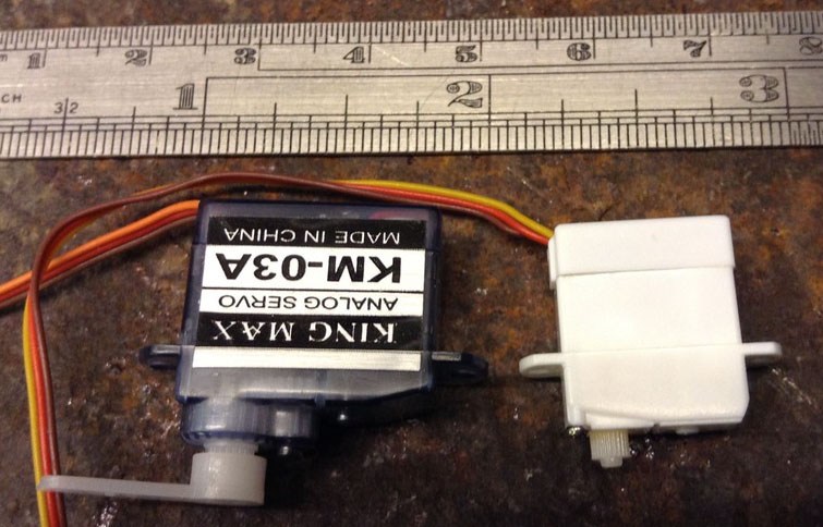
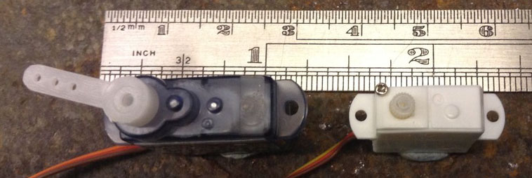
We have sourced some smaller servos which are the ideal size, but use a lower voltage so we just need to alter this.
If you’ve not heard of Tam Valley Depot, well neither had we until we started listening to Model Rail Radio which is a Pod cast hosted in the USA, it’s recorded live monthly and you can call in to talk about your modelling, but importantly a lot of manufactures and modellers from around the world also take part. We listen to it in the workshop and it’s amazing what knowledge you pick up.
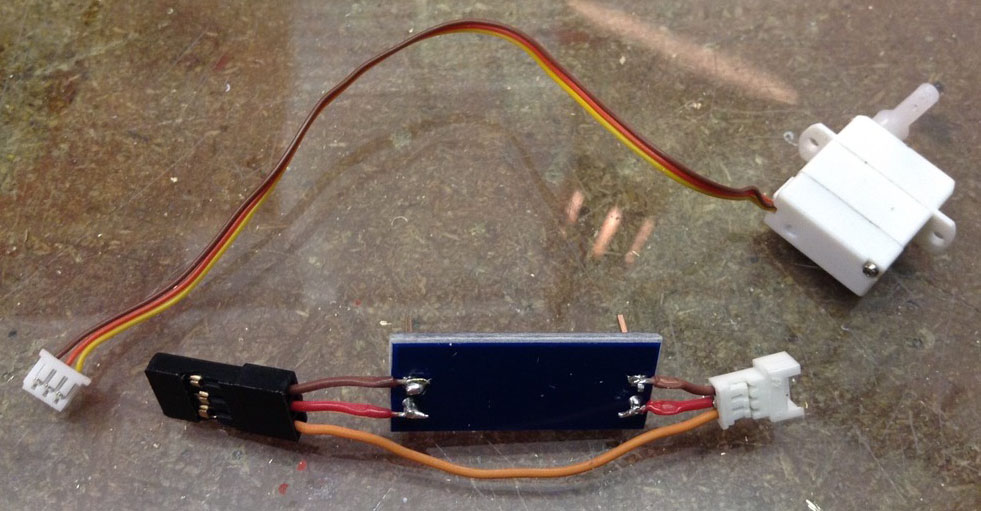
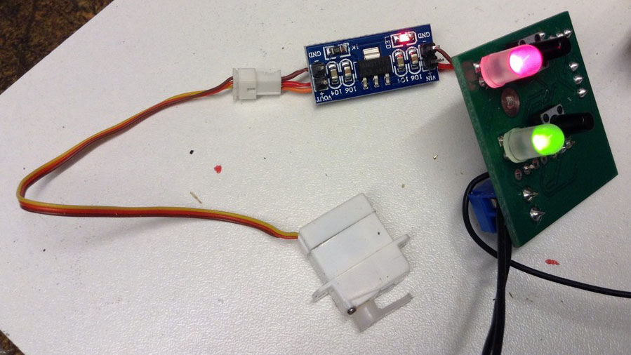
With the arrival of the boards one was wired into the converter lead, we didn’t use the plug type connector but wired to the bottom of the connector as we need to save space. Once the board is tested the plug terminals are snipped off.
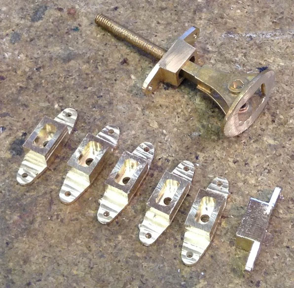
Darent’s couplings don’t use the self contained bodies like the Bredgar ones, because the springing is located behind buffer plate with a coupling pocket on the outside of plate. The pockets have been profile milled, the reason for six is four for the locos and two for patterns to cast.
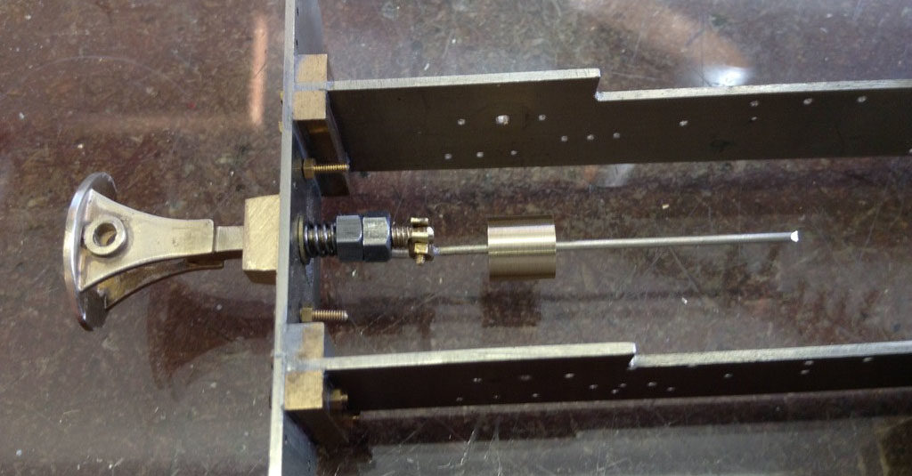
Using the design from the test couplings the coupling head was modified for the coupling bar and fitted to the buffer beam with a spring and washer, this allows the coupling to extend and also a small amount of sideways movement.
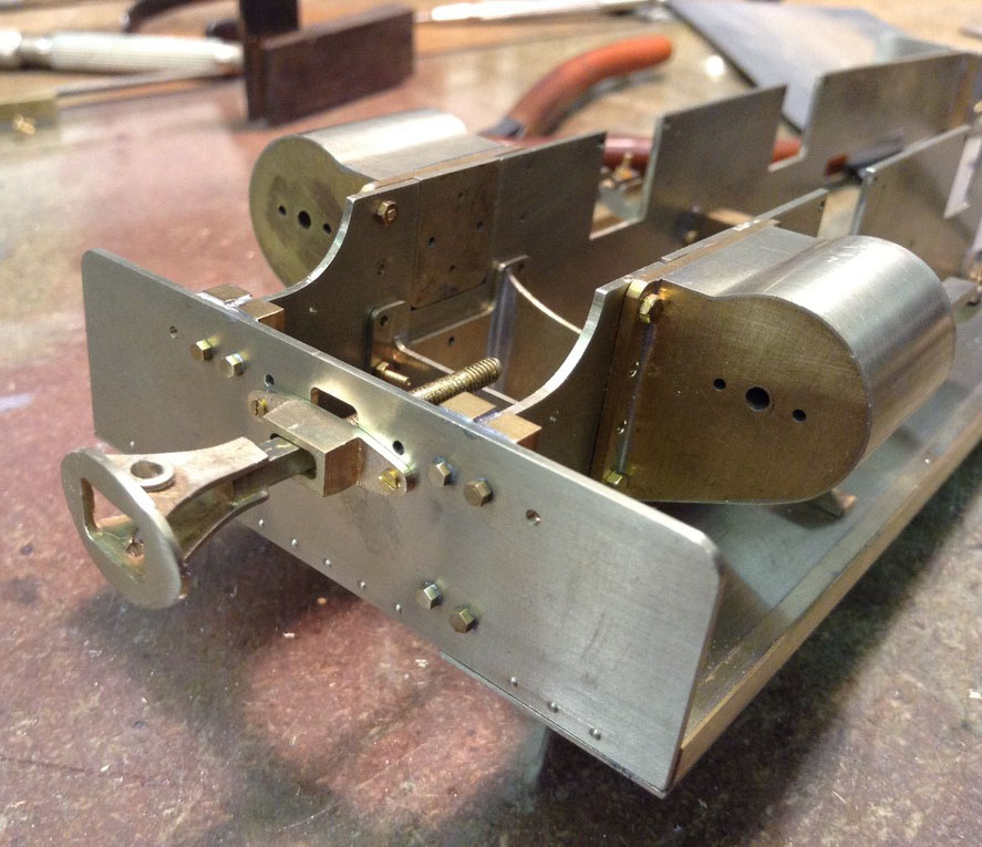
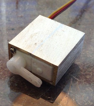
The servo fitting differed from the test one, its smaller and is encapsulated in a brass box which has the mounting bracket soldered to it, the reason for this is the plastic fixing points on the servo would protrude outside the the frames making them visible. The brass box was machined to fit the servo from square section.
Installed in the frames.
With the successful fit of the coupling and servo the other model can have it fitted as well, although we have quite a lot of electrical components it’s certainly been an interesting journey getting to this stage.