16mm as a scale offers a lot of possibilities especially with fine scale electric models, this scale is mostly garden type with live steam and robust track work but has seen a lot of interest lately in fine scale models.
A group of us run a small garden railway in 16mm live steam, and its from this that the initial inspiration to go 16mm fine scale sprang from.
This is going to be a scratch build, as other than the motors, gearboxes and bearings we will make all the parts ourselves.
We enjoy the whole process of scratch building more so than kit building as it gives you complete freedom to build as you wish.
The starting point for this project was to produce a drawing on clear drawing film, this material is more stable than tracing paper. The photo shows the setup for the saddle and cab on film with some white paper behind the film, photos of the film on it’s own don’t photograph well, but it gives the idea.
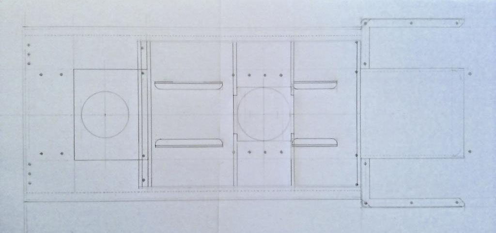
As a lot of the parts are cut out on a profile engraver, this dictates how the drawings are produced and yes we could draw it on CAD but we still like the drawing board.
The basic GA drawing is drawn twice model size at 32 mm/ft, on different layers so that each part can be checked and this ensures that the drawing doesn’t get too cluttered, the film make this very easy.
From this GA other parts are drawn to a larger scale, these can range from 3:1 upto 20:1.
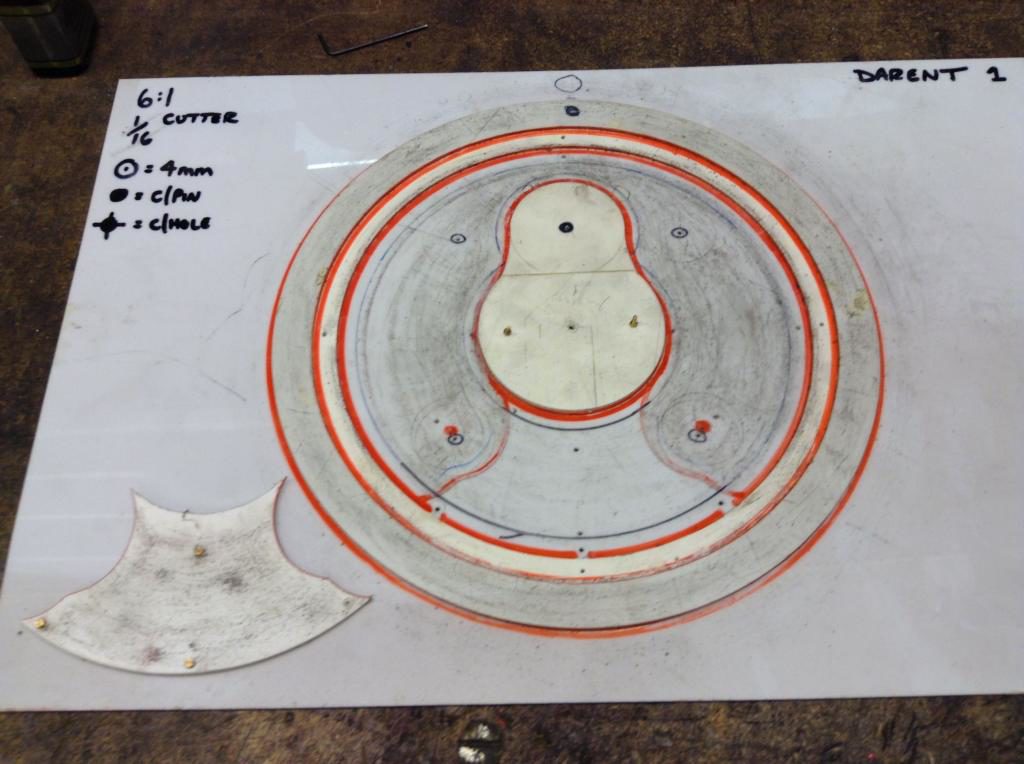
Once each section of the drawing is completed it’s checked again and the plastic patterns are marked out by pricking through the film into the plastic sheeting. This gives the outline on the sheet, which is then drawn again using the pin marks. The pattern is then cut from 40 thou and backed on to 60 thou plastic card, which is robust enough for the small run of parts needed for the build.
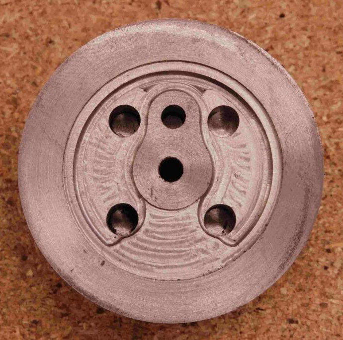
This shows the wheel pattern.
Wheels
The starting point on the build is the wheels which are solid casting on the real thing with bolted on tyres.
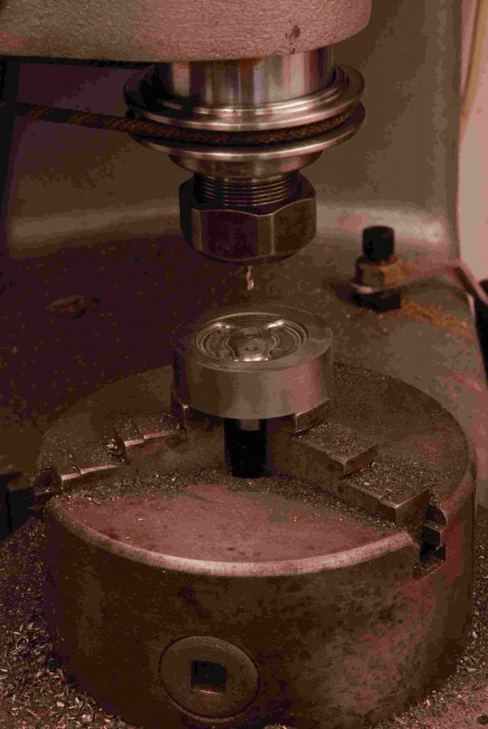
The model ones are cut from cast iron bar blanks and set up on a rotary table on the engraver to machine the details of the centres, and finished on the lathe just the same as the AGH type.
The machining of the front face contours involves some interesting machining which wasn’t without disaster on a couple of blanks, but we did cut more than needed. The leading and rear wheels are the same, other than the driven wheel has the balance weights cast in, this is shown on the pattern with the balance section removed. So the machining of the two is very similar using two varieties of slot drills, plain long series and bull nose types. The plain ones used in cutting the various levels and holes with the bull noise for the radiuses around the lower level peripheries on the crank web and outer rims. Some cleaning up was required mostly with some wet and dry to remove the cutter marks, other than two small wings of metal that couldn’t be reached, a small home made chisel made from old files soon removed them.
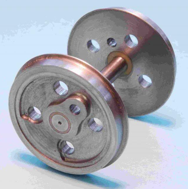
Completed wheel set. The down side of cutting cast iron on the engraver is the vast amount of dust it creates, the wheel patterns show the dirt on it. It’s not good for the rest of the machines in the work shop, which all needed covering.
Frames
With the basic wheels completed the next stage is the frames.
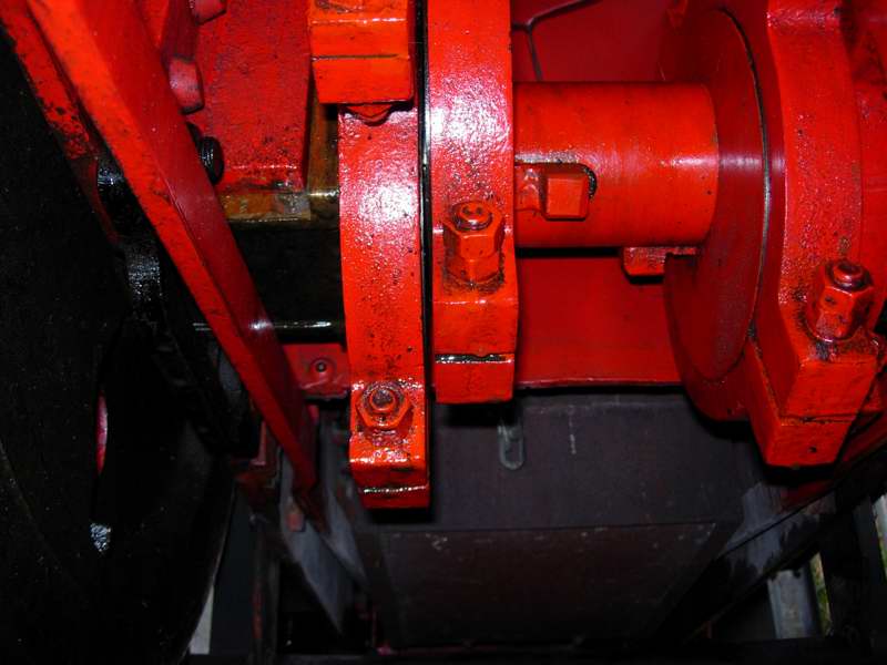
Working up the drawing for the frames involved the hornblocks, motor/gearboxes and inside valve gear.
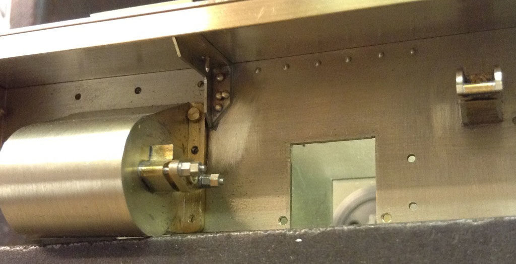
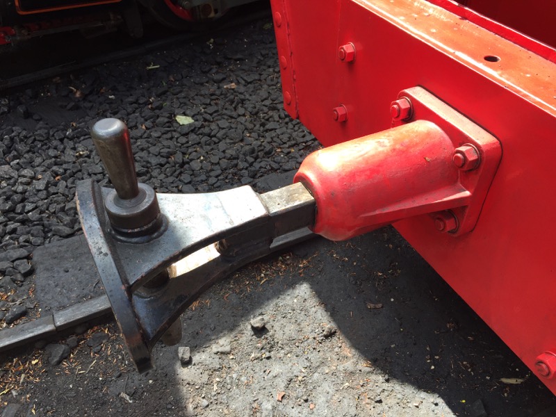
As we want the eccentrics to operate, clearance is at a premium with the motor mounted on the same axle, this photo of the full size loco gives the idea.
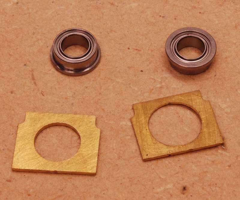
Giving models descent bearings with a limited width, moved us towards roller bearings, this we thought would be straight forward, but with most of the market flooded with cheap imports that have a very lumpy fill when rotating, our research paid off finding bearings made in Japan which have a press fit on the axles removing any play, although not cheap they are well made product.
With the bearings sourced the rest of the eccentrics could be drawn, although these have to be set closer to the bearings which is a compromise.
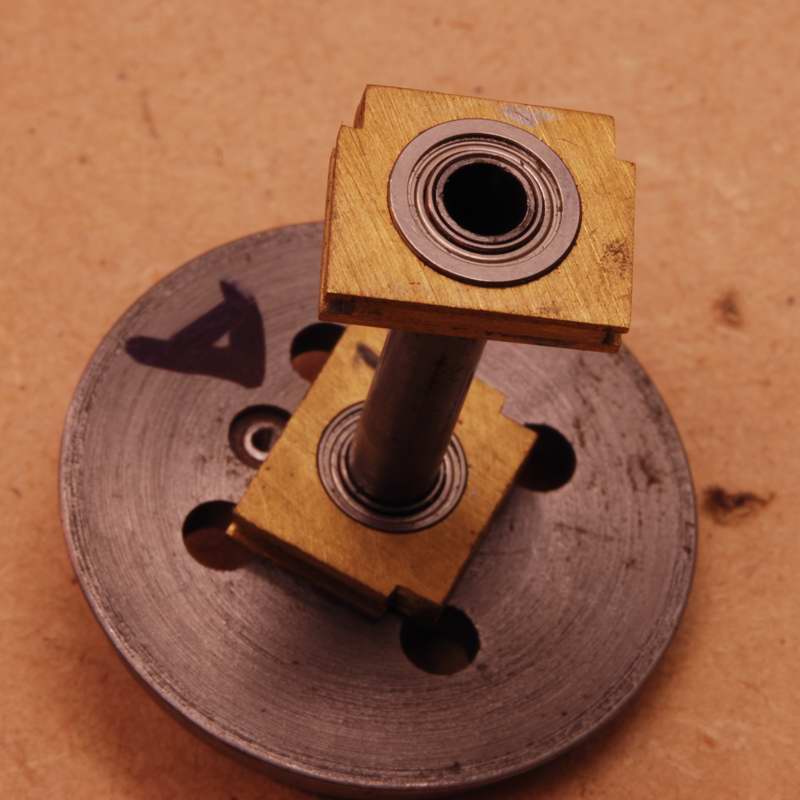
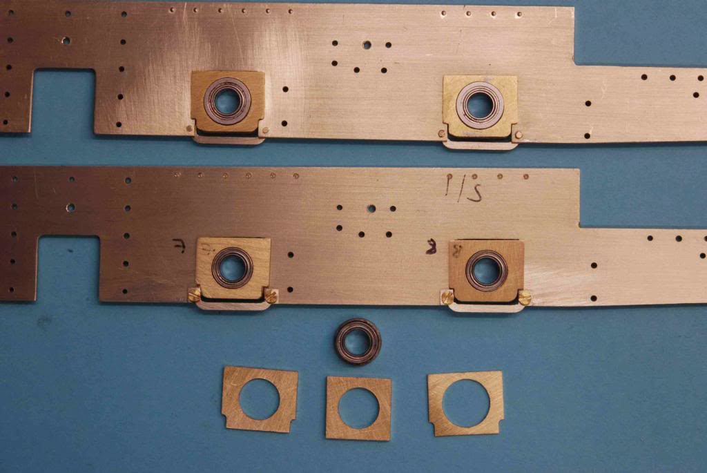
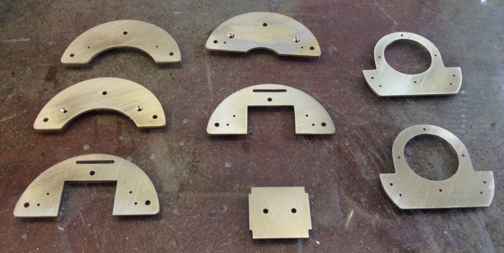
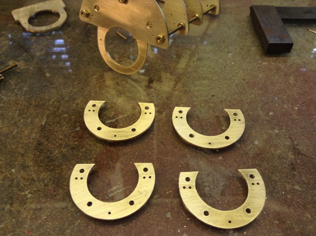
The bearings are encapsulated in three pieces of brass to give a slot to fit into the frames.
From the drawing the patterns for the frames, buffer plate and hornblocks are produced and cut out.
The frames and buffer plates from 0.9mm Nickel Silver and the hornblocks from 0.9mm and 0.4mm brass.
The rivet templates
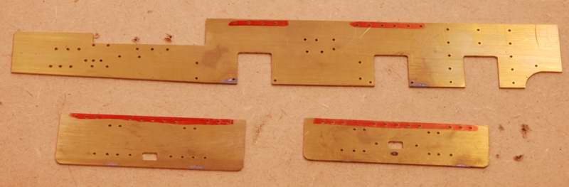
Both the frames and buffer plate have rivet details which can’t be pressed into 0.9mm material without distorting the plate work, to overcome this the position of the rivet has to be pre drilled to a depth of 0.7mm leaving 0.2mm which will form easily. All the rivet positions are drawn on the master drawing, from this some templates for drilling are made into patterns and cut out at the same time as the frames.
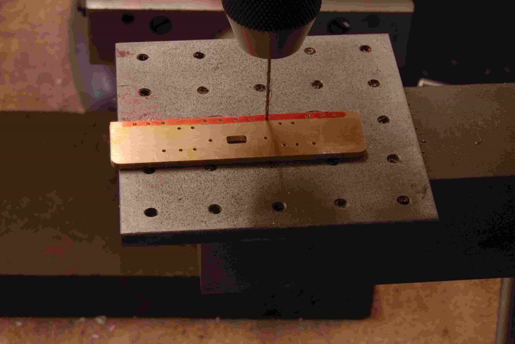
Drilling the rivet positions in the buffer beam that are marked in red, the other holes are for bolts.
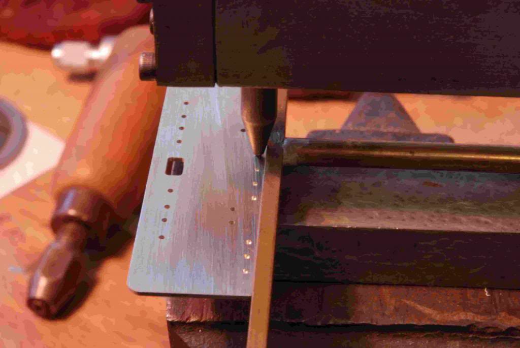
Riveting after pre-drilling.
Rivet detail showing on the top of the frames, bearings test fitted with the keeps.
Couplings
One of the common items of the stock is the couplers used on the locos at Bredgar.
For the development and build of the couplings see here.
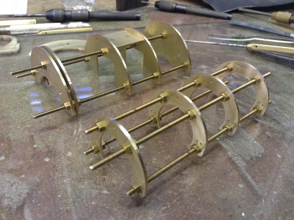
Boiler
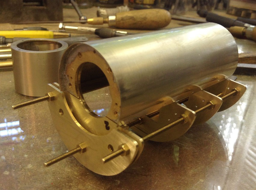
Building the boiler, saddle and smokebox assembly follows the same techniques used by most kit manufactures, this allows a rigid frame to fit the boiler and saddle skins.
Quite a lot of time was spent at the drawing board with these parts, time well spent when all the alignment holes line up.
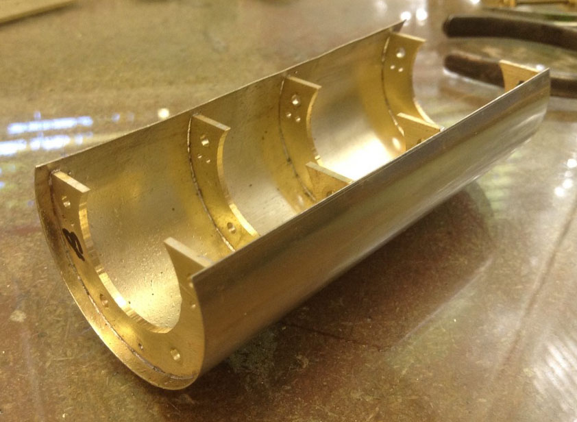
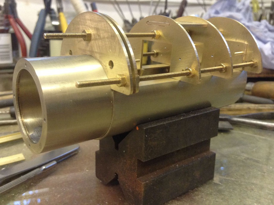
The frames have been profile milled from 1.25 mm brass, and are held together with 8BA studding which is removed once the skins have been soldered on.
The saddle, boiler and smokebox skins are made from 10 thou nickel silver, which has been rolled without any heat treatment to the metal.
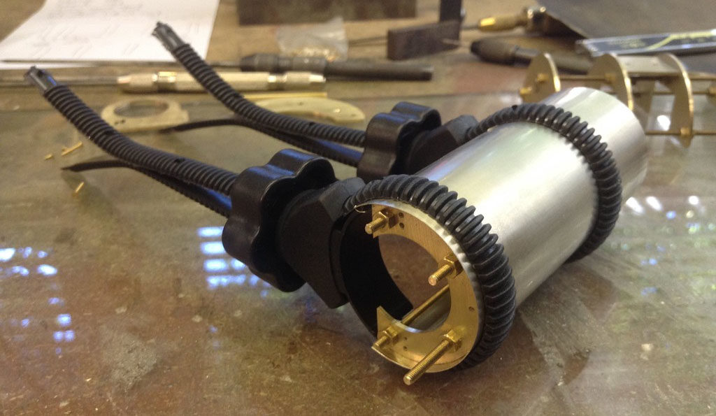
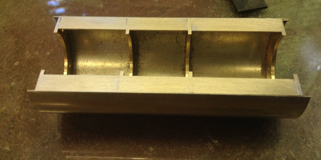
The design allows for the lower boiler section to be removed from the saddle, this will allow access to the sound chip and the associated wiring and will also make painting a lot easier.
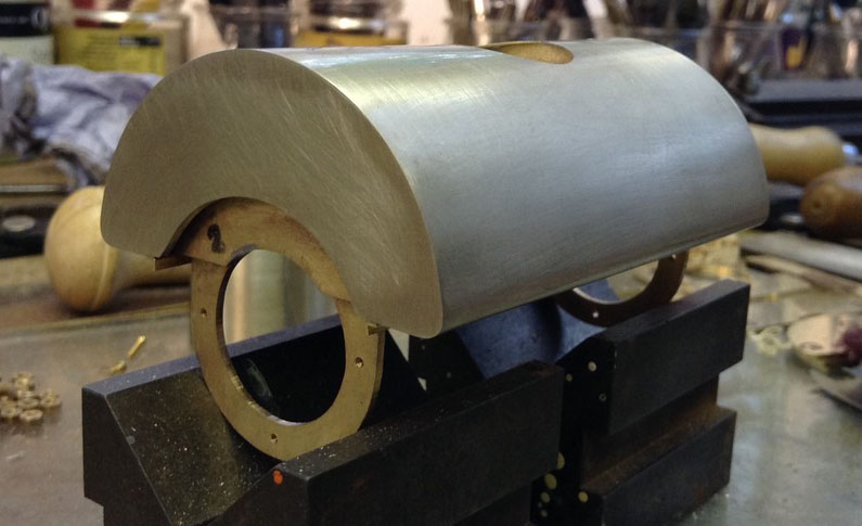
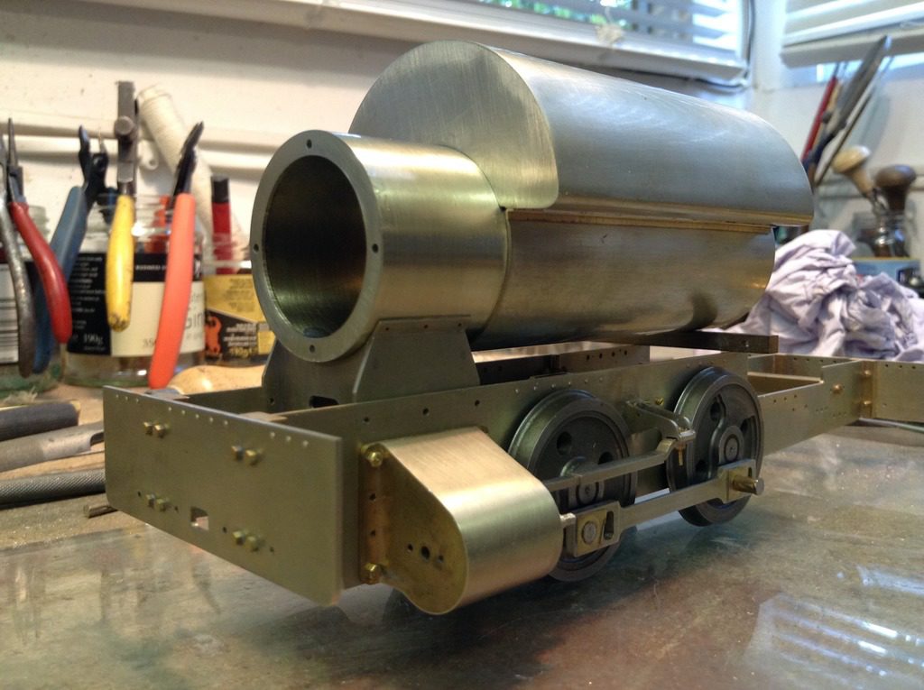
With the smokebox fitted, it’s beginning to look like loco.
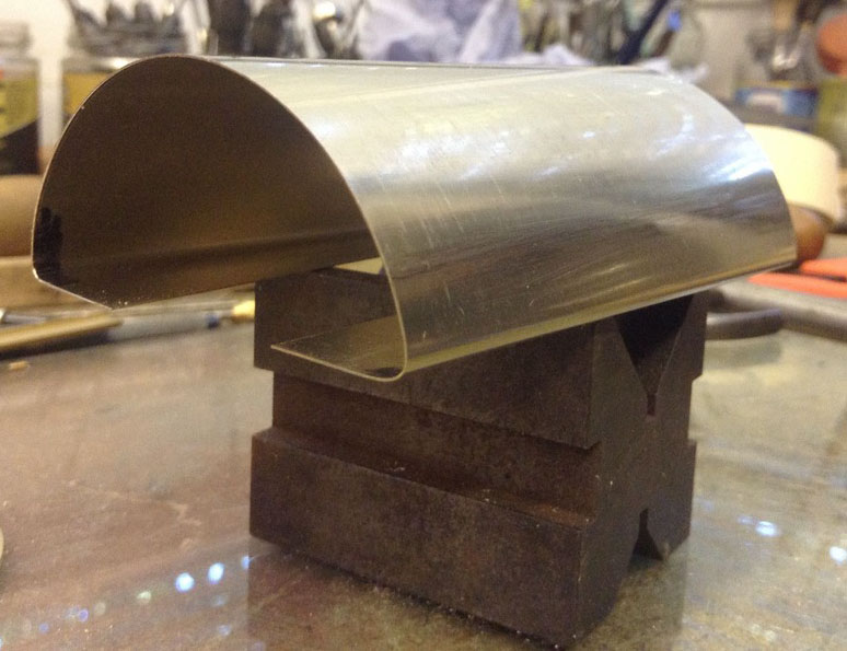
Saddle tank skin formed that’s the next job to fit.
With the saddle tank skin formed and on, its beginning to look like Darent. The smokebox has also been fitted and the saddle/smokebox test fitted on the frames.
Running plates
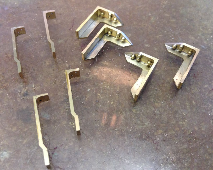
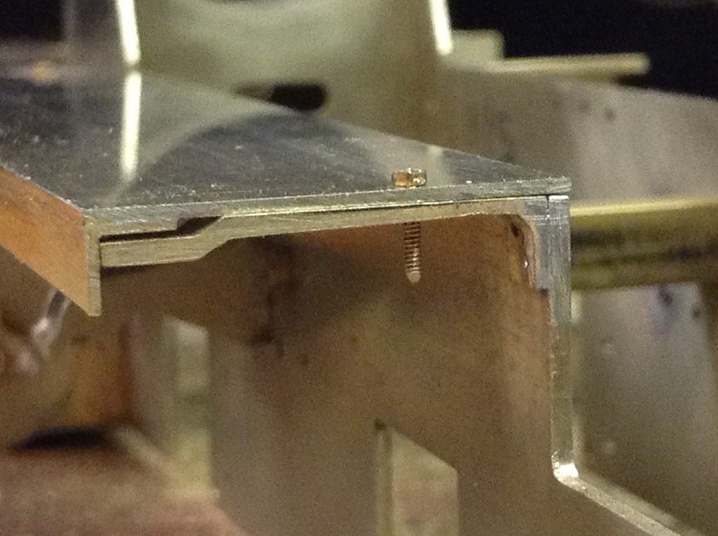
The running plates either sides of the loco are supported by two intermediate brackets, one with a strengthening plate and the other an L shape.
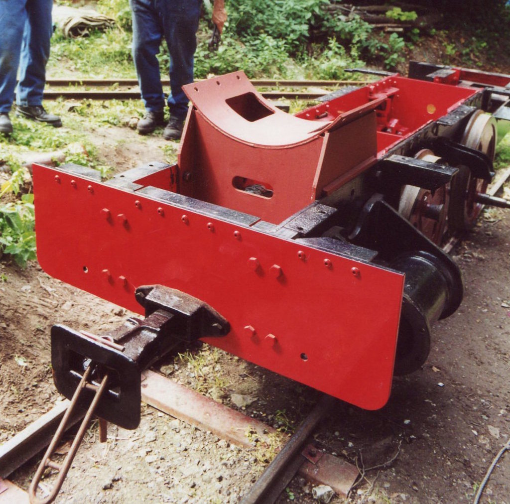
The full size Darent early on in its restoration showing the footplate brackets.
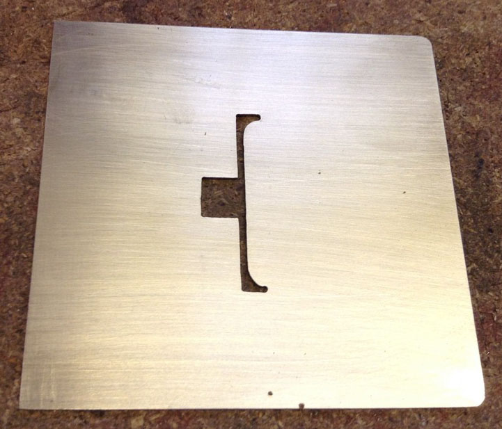
The running and foot plates have been cut out. On the foot plate the slot in the middle shows the shape of the boiler backplate and an access hole for the blowdown valve which is operated from the foot plate.
The motor when fitted will sit vertically inside the firebox, and as we are waiting for the motor gearboxes to arrive we have not cutout the footplate to accept it because we want to minimise the hole size around the motor.
Running plates fitted.
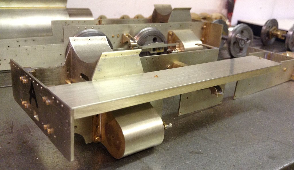
End view showing the fit of the brackets.
Underside view.